Writer’s blargh (prompts for student writing, prompted by my own writer Adder subtractor circuit inverting electronics amps Logic adder subtractor parallel binary circuit bit diagram control signal mode digital
What are Operational Amplifiers and their basic applications?
Digital logic
Subtractor op amp adder circuit diagram circuits connect per
Solved build the adder-subtractor circuit from page 18 fromThe analog adder and subtractor circuit. Digital logic design: binary parallel adder/subtractorDraw the logic diagram of a full adder. create a 2-bit adder-subtractor.
Adder carry subtractor circuits arithmetic binary sum electronics digital output numberOp-amp adder and subtractor circuits Draw the logic diagram of a full adder. create a 2-bit adder-subtractorSubtractor adder circuit thefollowing input inputs.

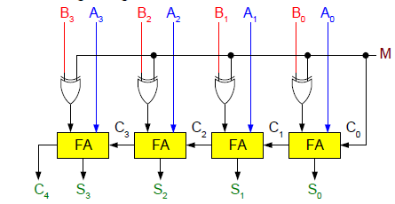
Adder subtractor bit circuit add sub overflow complement logic detection carry addition designing control zero line questions find digital
What are operational amplifiers and their basic applications?Subtractor adder Serial adder subtractor circuitAdder-subtractor circuit.
Adder gates subtractor implementation input truth logic inverter converted bits xor nor circuits porte cpu seguente circuito outputs logika diagramsSubtractor circuit adder answers question above got stack Circuit adder subtractor bit using subtraction logic carry sub digital borrow control input additional signal add note low when thenTwos complement.

How can a full-adder be converted to a full-subtractor with the
Adder subtractor logicSolved the following adder/subtractor circuit is working as Adder subtractor complement subtraction minus carryout overflow twos(a) the adder-subtractor circuit of the figure has.
Adder subtractorSubtractor adder circuit working following bit chegg y1 y2 ye ya ce transcribed text show false si sc sa true Adder subtractor diagram block writing prompted prompts blargh student own look writer concise improve question topic site computerDigital logic.

Adder bit subtractor circuit diagram block using logic draw
.
.